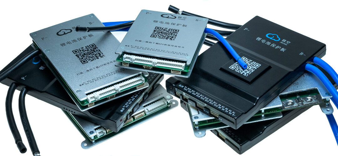
The board shown in the picture allows you to establish communication with inverters of the following companies:
- Pylontech (Deye) RS485/CAN
- Growatt RS485/CAN
- Voltronic RS485/CAN
- SRNE RS485
- Victron
This list could be updated, please ask for the current status and the possibility of connecting other inverters.
Only specially prepared BMS SMART DALY equipped with CAN/RS485 and LED12V connector can work with the board.

comboardoutlets
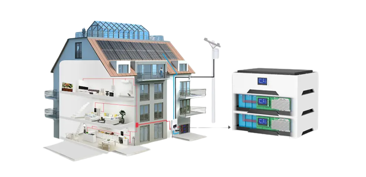
It is possible for the inverter to communicate with several batteries connected in parallel. Each of them must be equipped with its own BMS, parallel module and Comboard.
Communication with the inverter is possible via CAN or RS485. After selecting one of these standards, prepare a cable with RJ45 connectors to connect the board with the inverter. This wire must connect the corresponding connectors H and L (CAN) or A and B on the board and in the inverter (RS485 -GND is omitted).

comboard-powersupply
Please refer to the inverter manual or contact the manufacturer for the correct connectors on the inverter side.

wyjściacomboard
For example, if you want to connect the Voltronic inverter via RS485, you need to prepare a cable connecting pin 1 on the board (RS485-B) with pin 3 on the inverter, and pin 2 on the board (RS485-A) with pin 5 on the inverter.
Sequence of connecting the BMS to the inverter.
- Connect the board with the inverter using the prepared cable.
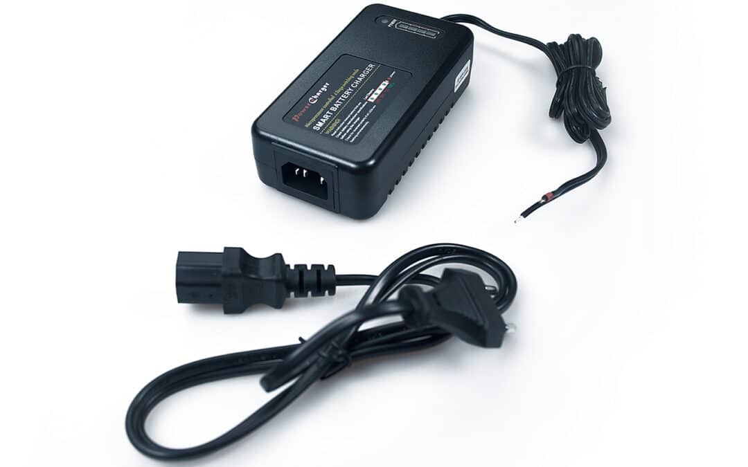
- Connect the power to the board through the supplied cable, which in the BMS connect to LED12V and start the board with the blue button.
- Connect a special RS485 (RJ45) cable for programming the board to a computer running the BMS DALY program.
- In the “Engineering model” tab, select the appropriate inverter protocol, connection type and restart the BMS. Note: It is not possible to select the protocol and connection type from the BT application or the standard RS485 cable connecting the BMS to the PC. This must be done through the Comboard connected to the PC.

comboardapp
For proper operation of the device, the correct setting of the inverter port may be required – please follow its instructions or information from the distributor.
The above information applies to the cooperation of one battery with BMS SMART DALY with Comboard board and inverter. If we want to achieve communication with several batteries connected in parallel (each with its own BMS and Parallel Module), we must use a Comboard board for each of them.
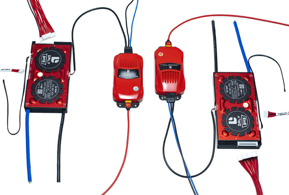
The first board connected as above is the “Master” and is connected to the inverter. Connect subsequent boards as “Slave” using the second communication channel. If we use CAN to connect the inverter, connect subsequent boards via RS485, if we use RS485 for the inverter, connect subsequent boards via CAN. Prepare the right amount of comboards and connecting wires.
An exemplary connection diagram of 4 boards (4 batteries connected in parallel), in which communication with the inverter is carried out via RS485:

przykładowy schemat połączeń
In the case of connecting several boards, similarly to the BMS connected to each other, they must be indexed. Each board must have its own unique number.
In the case of comboards, this is not done in the program, but by setting the switches correctly.
The table below shows which switch positions correspond to which board number.